Open laser focus position control system based on motion controller
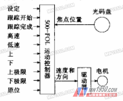
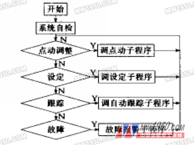
1 Introduction Figure 1 control system hardware block diagram It can be seen from the figure that the system and the CNC system are connected through the I/O port, accept the CNC I/O control commands to operate, have high versatility and flexibility, and can be connected and coordinated with any CNC system. jobs. Figure 2 Flow chart of the focus position automatic tracking system The jog subroutine is mainly used for debugging work and initial focus position alignment. Due to the different thickness of the steel plate, the distance of the laser focus from the surface of the processing object is different, so before each processing a new material, manually adjust the focal length, and then record the position of the sensor by setting the function as a reference for focus position tracking. point. Custom lamp fixtures are lighting fixtures that are specifically designed and made to meet the unique requirements and preferences of the customer. These fixtures can be tailored in terms of design, size, color, materials used, and functionality. Custom Lamp Fixtures,Custom Chandelier,Custom lighting,Project Lamp,lighting customization Zhongshan Seekyo Lighting CO., Ltd. , https://www.seekyolighting.com
Laser cutting uses a focused high-energy-density laser to act on the object, and the laser interacts with the object molecules to melt the object in the processing zone. As the speed of light moves, a slit is created in the object to achieve the purpose of cutting. Since the relative position of the laser focus and the processed object determines the size of the laser spot and the power density acting on the object, the relative position of the laser focus and the processed object plays a crucial role in the processing quality. How to maintain the relative position between the laser focus and the processed object during the laser cutting process is a reasonable and constant value, which becomes a key technology in laser cutting processing.
Studying the laser cutting focus position automatic tracking system can be considered in two aspects:
(1) How to detect the relative position between the laser focus and the processed object stably, reliably and conveniently
Laser processing is non-contact processing, and the focus position cannot be directly detected, and the focus position is determined by the distance between the focusing mirror and the surface of the processing object. Therefore, a common method is to detect the distance between the focusing mirror and the surface of the processing object, thereby indirectly detecting the relative position of the laser focus and the surface of the processing object.
Commonly used detection methods are divided into contact type and non-contact type:
The contact sensor consists of a mechanical transmission and some linear displacement sensors (usually inductive sensors) that convert the relative displacement of the focusing mirror and the surface of the object to a voltage for use by the control system.
The non-contact sensor is equipped with a capacitive and inductive eddy current sensor on the optical head, which uses the change of the capacitance or inductance of the sensor on the optical head to detect the relative distance between the focusing mirror and the surface of the processing object.
These two detection methods are for different applications. Capacitive non-contact sensors are mainly used in 3D laser metal processing applications because it is not convenient to use contact sensors. In other cases, it is more suitable to use a contact sensor.
However, both sensors are detected by analog signals, and during the laser cutting process, ionization is generated in the processing area to form electromagnetic interference, which has an influence on the detection result. Meanwhile, the response frequency of the inductive LVDT sensor is low. Affecting the dynamic characteristics of the control system, these are the issues that are urgently needed to be solved.
(2) After detecting the change of the laser focus and the position of the processing object, how to quickly compensate for the deviation, that is, the design problem of the position following system
The usual separate focus tracking system is implemented using the minimum system control stepper motor of the microcontroller. Because the performance of the single-chip microcomputer is relatively simple, it is difficult to implement a more complicated control strategy, and the dynamic characteristics of the ordinary stepping motor are relatively poor, which is difficult to meet the rapid requirements of laser focus tracking.
In order to overcome the above shortcomings, this paper introduces a laser focus automatic tracking system based on motion controller, which uses optical encoder as displacement sensor and uses the master-slave tracking (electronic gear) function of motion controller to achieve fast compensation of focus position error.
2 control system hardware design
The control system consists of a laser focus position sensor - optical encoder, controller - PARKER500-FOL motion controller and actuator AC servo system.
The optical code disc is the most widely used displacement sensor in the semi-closed loop numerical control system. Compared with the inductive displacement sensor, it has the advantages of good stability, good dynamic characteristics, strong anti-interference ability, and easy connection with the position controller. However, since the optical encoder is an angular displacement sensor, it is necessary to change the mechanical component to detect the relative displacement of the laser focus and the surface of the workpiece. We use the gear rotation associated with the rack drive and the optical encoder to achieve this conversion. The specific structure is not discussed here.
The PARKER500-FOL motion controller is a single-axis motion controller with position master-slave tracking function. In addition to the function of the general motion controller, it also has the function of automatically tracking the position of an optical encoder signal. Automatic tracking of the laser focus position during automatic machining can be realized, and various operations during jog adjustment can also be realized.
Since the 500-FOL motion controller can only output two pulse signals or pulse and direction signals, the drive can only use an all-digital servo system with pulse input.
The hardware block diagram of the whole system is shown in Figure 1. 
3 Workflow
Since the laser focus position tracking system is part of the overall laser machining control system, it must be controlled by the CNC master system, which is the slave system.
(1) After the system is powered on, the 500 motion controller automatically controls the motor back to the mechanical position and waits for the CNC control command.
(2) The CNC can send a jog adjustment command to the 500 motion controller through the I/O port to adjust the initial position of the laser focus.
(3) The initial position of the focus is set by the setting command as the reference value for the focus position tracking.
(4) During automatic machining, the CNC can issue different commands as needed, allowing the system to automatically track changes in the surface of the machined object, or to end tracking.
(5) In order to prevent the optical head from colliding with the processing object, the optical head should be moved a certain distance when the tracking is completed, and the focus position should be automatically found at the slow speed in the next tracking.
Under normal circumstances, the jog adjustment can be completed by the panel switch, and the automatic state is output by the CNC M code after the PLC control output focus position tracking system.
4 control process
The PARKER500-FOL motion controller adopts a mixed programming method of logic control and motion control, which is automatically executed according to the control program after power-on.
Since the focus position automatic tracking system and the main control system exchange information through the I/O port, it performs corresponding actions according to the control command of the I/O port. The focus position automatic tracking system is to perform the actions specified in the flow chart shown in FIG. 2. 
During the machining process, the numerical control system performs the tracking, holding and deregistering functions according to the different M codes of the numerical control program through the I/O port control focus position control device. Considering that the machining process may pass through the cut-out part, the focus position tracking function should be turned off at this time to prevent the laser cutting optical head from falling into the hole formed by the cutting and being damaged. In addition, considering the change of the surface of the processing object, the optical head should be lifted for a distance while the tracking function is turned off, and the focus is automatically aligned when the automatic tracking function of the focus position is turned on.
5 Summary
Since the optical encoder is a digital displacement sensor, the detection stability is higher than that of the inductive LVDT displacement sensor; the PARKER500 motion controller has a very high sampling frequency for the optical encoder, so the optical encoder sensor and the PARKER500 motion controller are used. Combined detection can greatly improve the response speed of the system; the effective position control algorithm of PARKER motion controller can ensure that the master-slave tracking error is within a few wires, which can fully meet the requirements of laser cutting focus position accuracy.
There are various types of custom lamp fixtures that can be created, including: Pendant lights, Table Lamp, Floor lamps, Wall sconces, Chandeliers, Task lighting fixtures.
Custom lamp fixtures offer the opportunity to have unique and personalized lighting solutions that perfectly match the individual's taste and requirements. They can be created by working closely with lighting designers or artisans who specialize in custom lighting.