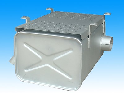
Machining analysis of automobile muffler end cover mould
Process analysis of automobile muffler equipment end cover mold parts The principle of the automobile muffler end cover processing technology plan is to optimize the combination of the process and reasonable arrangement of the stamping process to ensure the quality of the product parts, improve the production efficiency, and satisfy the large quantity. The requirements of production, after analysis: a single piece of machining must determine a reasonable assembly clearance to ensure that the parts are riveted after forming. The processing order of each piece is determined as follows: 1 the upper cover is the blanking-shaping-cutting-cutting-punching hole; 2 the clamping plate is the blanking punching composite die: 3 the bottom cover is the blanking-stretching-shaping-shooting Hole - Flange - Crimping - Riveting. It is worth noting that the four rounded corners of the cut of the sole cover have a great influence on the quality of the riveting process. It is an important dimension for the uniformity of the transition along the circumference after riveting. Therefore, the unfolding size can be determined after trial production. Calculated as R26mm, the actual processing is R29mm. Ningbo Alite Lighting Technology Co.,Ltd , https://www.alite-tmwt.com
Automobile muffler equipment end cover mold main processing technology analysis Automobile muffler is a variety of models, the shape of the bottom cover and the upper cover is complex. The height is uneven and the degree of deformation is inconsistent. According to the stretching coefficient m=d/B and the relative height H/r of the workpiece is close to the degree of deformation of the initial stretching, it is difficult to succeed once, in order to make the workpiece can be stretched once. , can also ensure a smooth transition of the workpiece. No wrinkles and cracking. The following measures have been taken: 1 appropriately increase the radius of the drawing die to facilitate the flow of metal, reduce the radial tensile stress which causes the tensile crack and the thickness of the material; 2 appropriately increase the pulling of the male and female die The extension gap (take 1.2t=O.6mm) can improve the inconsistent flow resistance of the materials due to the asymmetry of the shape, ensuring the balance of material flow resistance, so that the workpiece will not be cracked; 3 the straight wall side and R are tangent to the punch There is a slight concave phenomenon at the round corners. The reason is that the material that is rounded by the die is not uniformly thinned, and the straight wall near the flange is bent and the wall thickness changes little. Close to the rounded part of the deformation is large, belonging to tensile deformation. Therefore, the thickness of the material is inconsistent, and it is easy to form a bonded tumor during the shaping process and the workpiece is pulled. Therefore, the surface finish of the drawing and shaping sequence must be very high. The punch and the die are made of Crr2MoV, the quenching hardness is 60-64HRC, and the diesel oil is used. The oil is applied to the pressure ring with a 7:3 mixed lubricant and the concave mold cavity and the upper surface of the workpiece.
