Screw pump test considerations
Abstract: This paper proposes a networked video surveillance system that combines MCU control technology, USB data acquisition technology and computer network structure based on TCP/IP protocol stack, enabling people to monitor video and audio such as cameras and microphones on site. The capture device transmits the signal from the monitoring site to the monitor via a local area network and sends it to the monitor for real-time image and sound.
Keywords: embedded system; local area network; real-time monitoring
With the rapid development of embedded systems, in many areas, microcontroller-centric applications are gradually replacing computer-centric applications. Therefore, for the research of network application systems, more and more researchers have shifted their research focus to embedded systems. Based on this background, this paper proposes a networked video surveillance system solution, the goal of which is to enable people to transmit signals from the monitoring site to the monitor via the local area network by monitoring the video and audio capture devices such as cameras and microphones on site. Get local real-time images and sounds for remote viewing.
How the system works
In this monitoring scheme, the embedded host system uses TI's mixed-signal microcontroller MSP430F1611 as the system core controller, the USB host interface chip uses Cypress's USB Host/Slave interface chip SL811HS, and the Ethernet transmission chip adopts REALTEK's Fast Ethernet control chip RTL8139, the system's regulator source selects NS's LM1117.
When the system works, the MSP430F1611 and SL811HS control the camera as a USB slave device, and read in the video data to process and store it. At the same time, the audio data in the microphone is read into the MSP430F1611 for data conversion and storage. Then, the IP datagram encapsulated by the transport layer and the network layer is encapsulated into an Ethernet frame by the RTL8139, and then transmitted to the local area network through the Ethernet transformer PE68515.
System block diagram
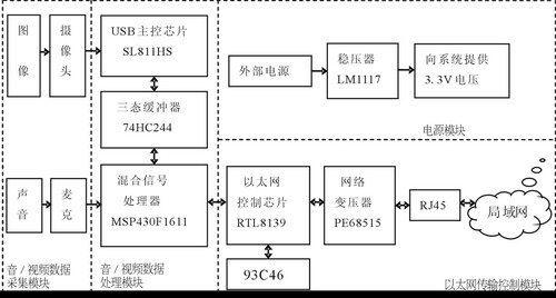
The whole system consists of four parts: audio/video data acquisition module, audio/video data processing module, Ethernet transmission control module and power module, as shown in Figure 1.
Figure 1 System block diagram
(1) Audio/video data acquisition module: This module is mainly composed of a camera, a microphone and its peripheral circuits. The camera is mainly composed of lens, image sensor and digital signal processing chip ZC0301P, which completes the acquisition, conversion and transmission of image data. The transmission speed of VGA video image can reach 15 frames per second. The microphone is mainly used to collect analog sound signals.
(2) The audio/video data processing module is mainly composed of MSP430F1611 and SL811HS, which completes data acquisition and processing. The embedded USB master/slave interface chip SL811HS and the 16-bit microcontroller MSP430F1611 follow the USB1.1 protocol to implement the USB host function and have a USB bus interface. The module is integrated into the user's embedded system as a data interface module to process and store the data read in the camera and microphone.
(3) Ethernet transmission control module: The main task is to transmit the IP data packet after the transmission layer and network layer packet to the Ethernet packet through RTL8139, encapsulate it into an Ethernet frame, and then transmit it to the local area network through the network transformer PE68515.
(4) The power module supplies 3.3V to the system after the external power supply passes through the LM1117 regulator according to the power requirements of each device in the system.
System hardware design
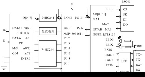
In this design, the MCU uses MSP430F1611, which has 48KB+256B FLASH memory and 10KB RAM. MSP430F1611 and SL811HS mainly complete system data acquisition and processing functions. The hardware interface block diagram of MSP430F1611 and SL811HS is shown as in Fig. 2.
Figure 2 system hardware interface circuit block diagram
In Figure 2, the M811 of the SL811HS is tied low and operates in master mode. CM is tied low to make the system work at 48MHz. Since the MSP430F1611 is connected to the SL811HS and connected to the RTL8139, the SL811HS pin itself has no tristate function. Therefore, a tristate buffer 74HC244 needs to be added between the MSP430F1611 and the SL811HS to achieve the purpose of three-way communication. The SL811HS is connected to the I/O port of the MSP430F1611 through a buffer; the interrupt request terminal INTR0 is directly connected to the I/O port P1.1 of the microcontroller, and the SL811HS generates a high level output after the data is transmitted. The status of the device is detected by the MCU timer, and if the slave device is found to be connected, an external interrupt is triggered.
Most of the pins of the MSP430F1611 function as I/O ports and are mainly used to communicate with the SL811HS and RTL8139.
The function of the communication between the MSP430F1611 and the RTL8139 is to process and store the audio/video data transmitted from the upper application, and then perform the data encapsulation process, and the stored data is encapsulated into a UDP (User Datagram Protocol) data packet through the network. The layers are encapsulated into IP data and encapsulated into Ethernet frames through the data link layer and then transmitted to the destination over the physical network.
System software design
The software part of this design mainly includes the acquisition module software design and the Ethernet transmission module software design. The device status is detected by the MCU timer. If the system finds that the slave device is connected, an external interrupt is triggered. After the slave device discovers, device enumeration is performed through the SL811HS, the device address, data description and configuration are set, and then the slave device file system is accessed through the mass storage protocol.
The Ethernet transmission module interrupt subroutine flow chart is shown in Figure 3. The reception of RTL8139 data is completed by interrupt mode. When the main processor sends data to the network, the first frame of data is sent to the controller's transmit buffer through the DMA channel, and then the transfer command is issued. The RTL8139 transfers the data from the transmit buffer to the internal transmit FIFO according to the PCI bus master mode. When the data packet in the FIFO is complete, the RTL8139 starts packet transmission. The controller notifies the main processor by interrupt after the data transmission is completed. When receiving data, the data packets transmitted on the network are first placed in the receive FIFO, and the RTL8139 is used for address filtering. When the data packet in the receiving FIFO has reached the requirement of receiving the configuration register, the RTL8139 requests the PCI bus to transmit data to the receiving buffer according to the PCI mode. After receiving one frame, the RTL8139 also notifies the main processor of the state of data transmission and reception in an interrupt manner.
Conclusion
This design is mainly for the application of home security, the system can finally achieve a data transmission rate of 8 ~ 10Mbps. With the increasing popularity of network applications and the continuous development of embedded systems, more embedded network products will emerge in the future. â– 

references:
[1]. MSP430F1611 datasheet http://
[2]. SL811HS datasheet http://
[3]. RTL8139 datasheet http://
[4]. LM1117 datasheet http://
[5]. VGA datasheet http://
[6]. 74HC244 datasheet http://
[7]. PCI datasheet http://
:
With a global reach, huge inventory, excellent warranties and great customer service, you won't find a better place to purchase Final Drives.
With our great products, you know you will be receiving Quality parts at great Value. We make sure our customers get the lowest price on the market. We also offer fast Free Shipping and a Lifetime Replacement Plan with every purchase.
Hitachi Final Drive,Hitachi Final Drive Assy,Hitachi Travel Motor,Hitachi Travel Gearbox,Hitachi Final Drive Spare Parts,Hitachi Drive Parts,Hitachi Motor
Jining Juheng Hydraulic Machinery Co., Ltd. , https://www.sdjuhengmachine.com