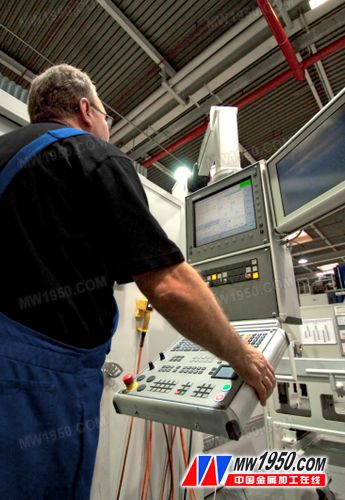
HEIDENHAIN iTNC 530 new user features
Dynamic Collision Monitoring (DCM-Software Option) Save all grips and recover. This feature is very advantageous for the combined fixture system because it avoids the measurements required when the entire fixture system is reinstalled to the machine. Another new feature is the ToolholderWizard, which is used to easily enter toolholder parameters, such as angle milling heads, with dialog help when entering. This avoids collisions between the tool holders of different tools and the permanent parts of the machine: only the corresponding files and probes are associated in the tool table. KinematicOpt: Check and compensate for machine error (software option) It is now also possible to measure the misalignment of the angled milling head (milling head or table). The axis of rotation of the milling head shaft is measured twice, each time with a stylus of a different length. A calibration cycle 460 has also been added because the stylus must be replaced between the two measurement cycles. The HEIDENHAIN reference ball to be used in the new calibration cycle 460 has begun to be available. The measurement function of the spindle head connected to the ratchet is also improved. If the machine manufacturer integrates the NC macros in the calibration cycle, it is now also possible to position the spindle heads with NC macros. It is now possible to determine the backlash of the rotary axis more precisely. If an angle value is entered in the new Q432 parameter of cycle 451, the TNC will rotate the axis at each measurement point position using the motion that determines the backlash. New cycle 275 (cycloid groove) This new cycle is used to easily and efficiently machine closed and open slots and any desired contour slots. The cycle first performs rough milling, that is, cycloidal milling. The sides are then trimmed so that the "saw teeth" formed in the roughing are cut off. What is the working principle of cycloidal milling? The roughing process includes a cycloidal motion (Greek "trochos" = wheel). That is to say, the TNC calculates the milling path, which is the path formed by the superposition of the linear forward motion and the circular motion of the milling cutter. The kerf milling has a large depth of cut and a fast cutting speed because the cutting conditions are evenly distributed, so that the adverse effects of fast tool wear can be avoided. On the other hand: if the blade is machined, the entire cutting length is available, so the single-edged cutting amount is large. Not only that, it is the easiest way to achieve machine tool mechanics. If this type of processing is used with the Adaptive Feed Control (AFC) option, it will save a lot of time. New 3-D radius compensation with 3D-ToolComp (software option) The compensation value table defines the angle-dependent difference, which describes the deviation of the tool from the ideal circle. Then, 3D-ToolComp corrects the corresponding radius value with the current contact point of the tool and the workpiece. In order to accurately determine the contact point, the CAM system must create an NC program with a surface normal vector block (LN block). The surface normal vector block determines the theoretical center point of the radius milling cutter and sometimes the direction of the tool relative to the workpiece surface. The best way to fully define the compensation value table is to measure the tool shape with a special cycle and laser system so that the iTNC can use the meter directly. Improve tool management (software options, machine related functions) The tool and magazine information is displayed more clearly. Many new features are available: add and remove tools by dragging and dropping the mouse. The tool usage list shows the workpieces machined by each tool. Another feature is that the table structure is more reasonable, with different colors representing different tool states. Program selection Now, when calling the program with PGM CALL, select the desired program in the pop-up window. The TNC automatically enters the path name. 3-D line diagram The 3-D line graph display can also be displayed in full screen, and the detail display is clearer. PLANE function When tilting to a position with the "Rotate" function, enter the MB retraction distance (backward movement) and move just before the limit switch (MB MAX). Manual alignment In the manual scan cycle, the misalignment measurement of the workpiece is compensated by rotating the rotary table. Q parameter programming The jump address can now be defined with the QS string parameter, for example IF = 0 GOTO LBL QS99. Leather Storage Cabinet,Leather Dresser Storage Tower,Drawer Storage Tower Chest,Stackable Drawer Storage Tower Changzhou Offistyle Furniture Co., Ltd. , https://www.offistyledesks.com