EdgeCAM high-end turning and milling composite machining center application (2)
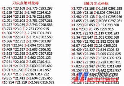
For high-end turning and milling equipment with B-axis function, better machining surface quality can be obtained by B-axis swing angle positioning or XYZBC five-link machining (as shown in Figure 2). At the same time, this type of equipment can also complete the processing of more complex impeller blades (as shown in Figure 3). Most of the milling and milling equipment comes with some programming functions. For example, the Mazak matrix series and the HEIDENHAIN CNC PILOT 3190 series control system have interactive programming functions of human-machine dialogue, which can not only complete two-axis turning, but also complete C&Y auxiliary power. The conventional milling machining of the head is programmed, but there is nothing that can be done for machining parts with complex profiles. At this time, it can only be realized by means of CAM software. Therefore, for the high-end turning and milling processing equipment with turning and milling compound, especially with double turret, it is necessary to exert its proper performance, and it is inseparable from the support of CAM software. However, in the application process of CAM software, the formulation of post-processing is particularly important. Due to the existence of the rotation angle coordinates, when programming in the CAM software, people are accustomed to using the absolute coordinate programming mode of the tool tip point. When the generated NC code is running on the machine tool, the control system needs to have the function of three-dimensional tool length compensation ( As shown in Figure 4, the control system automatically implements tool length compensation in three dimensions based on the actual tool length L2. (Note: In fact, when the control system is in compensation calculation, the calculation is based on the value of L1+L2, and the value of L1 can be set directly in the machine system parameters after the machine tool is commissioned). If the control system does not have the 3D tool length compensation function, you need to measure the length of the tool on the tool setting tool beforehand, and then specify the tool length parameter in the CAM software environment before generating the machining program. The coordinate points in the NC code actually generated. It is the coordinate of the center of rotation. Such a program must use a tool of the specified length during the application. (At the end of the last century, when the control system did not have the 3D tool length compensation function, this method was used to complete the five-axis coordinate program. To facilitate the use of the tool, a retractable sleeve was usually added to the machine spindle. Parts to adjust the tool length to the tool length set during programming). Whether it is absolute coordinate programming or rotary center coordinate programming, for the turning and milling center, the B axis has a special processing method as a linkage axis, that is, the B axis coordinate following function. Let's take the tooltip absolute coordinate programming as an example. Let's look at the difference between the B-axis coordinate following function program (the B-axis coordinate following function can also use the rotary center coordinate program, which is not discussed here). The B-axis coordinate following function differs from the tool nose point absolute coordinate programming in the rotation of the coordinate system (as shown in Figure 5). If the B-axis coordinate following function is used, the Z-axis always follows the current position of the tool, but always points to the spindle. The direction of the axis, so that when solving the three-dimensional tool compensation, the amount of calculation of the control system hardware is reduced accordingly, and more calculations are done under CAM software. This mode therefore saves control system resources to meet the high demands of control systems for complex part machining and high speed machining. The following is a comparison of a program that uses the B-axis coordinate following function with a program that does not use this function: It can be seen here that in the two modes, the rotation coordinates in the program are the same, but the linear coordinates are different, that is, the position of the tool tip point changes with respect to the value of the current coordinate system. The B-axis coordinate following function is normally implemented by a pair of G code commands. The view on improving the efficiency of turning and milling combined machining and multi-axis linkage of turning and milling cannot be discussed in more detail because of the limitation of space. More and more practice in the field of turning and milling combined machining will bring us more available. Thinking about the subject, but we found that in the turning and milling complex machining, many turning and milling functions require the CAM software environment to support, so for a high-end turning and milling equipment, CAM software is one of the essential tools. Previous page Stainless Steel Door Handle,Stainless Steel Handle,Kitchen Cabinet Door Handle,Door Handle Stainless Steel Wenzhou Shenghong Metal Products Co.,Ltd , https://www.shenghonglock.com
